ABAQUS Project 00 Notes
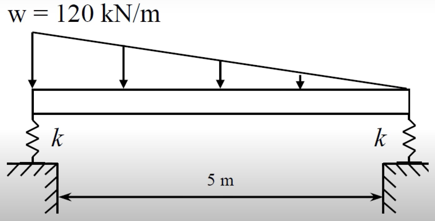
Rectangular beam with 500mm x 300mm cross sectional area. k=50MPa
Unitless interface requires consistency in units. We will use SI for simplicity.
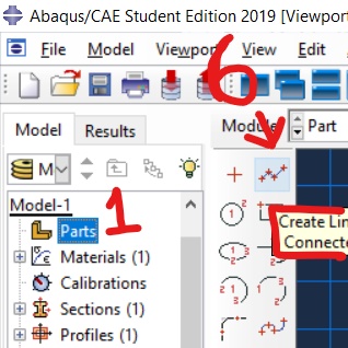
- Select Parts. Select 2D Planar.
- Name: beam
- Type: Deformable
- Base Feature: Wire
- Approximate Size: 10
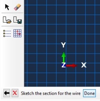
- Select Create Line. Create line 5 long. Select done.
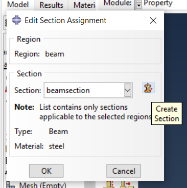
- Parts>Beam>Section Assignments>Left click beam>Name Set Beam>
- Name Section: Beam. Select the line created previously to highlight red. Select Done.
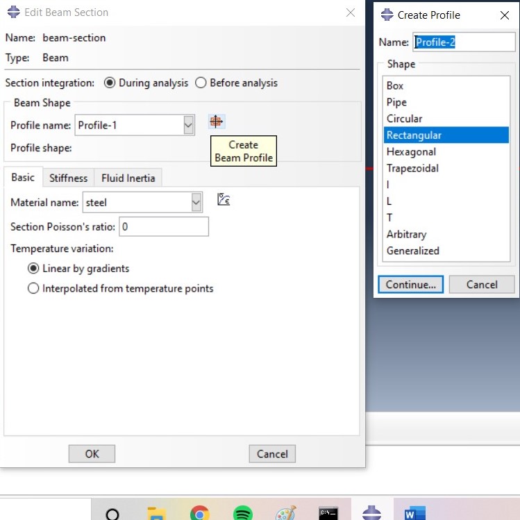
- Select Create Section Icon. Name Beam-Section.
- Select Create Beam Profile Icon: Rectangular. Name: rect
- For 300mm by 500mm enter 0.3 and 0.5
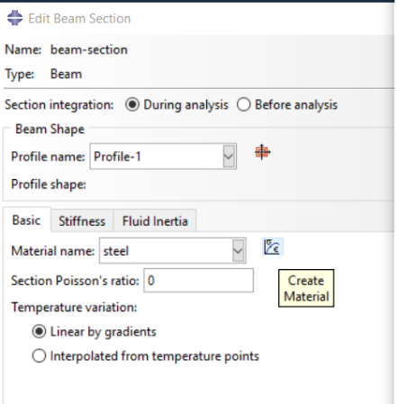
- Select Create Material Icon
- Mechanical>Elasticity>Elastic
- Youngs Mod: 210e9
- Poisson: 0.3 (no difference will be made in 2d model but still needs to be filled)
- OK. OK. OK.
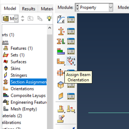
- Select Assign Beam Orientation. Left click line or select sets and select beam set made in step 7. May manually input vector but 0,0,-1 suffices. To accept, click enter and OK.
- To view beam: View>Part Display Options> Render Beam Profile. This is just an exercise and one may return the beam to the default viewing method after finished
- For springs: Parts>Engineering Features>Springs/Dashpots
- Select Connect Points to Ground (Standard)
- Hold shift and select both ends of line. Select OK and Done or hit Enter. Select Degree of Freedom: 2. 1 DOF for axial forces, 2 for bending, and 6 for rotational. Insert 50e6 for k=50MPa
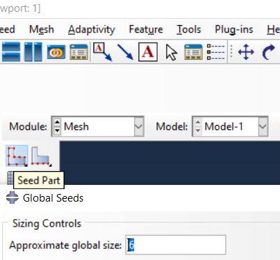
- Engineering Features>Mesh>Seed Part
- The standard mesh size works fine for this exercise. Finer the mesh, the longer the calculation takes to run but the higher quality the results
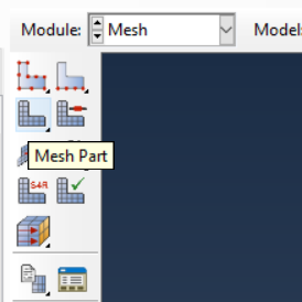
- Select Mesh Part. Yes.
- One may choose between the machine code formulation (Shear Flexible) or Euler’s formulation (Cubic Formulation) in Mesh>ElementType>SelectBeam>SelectDone
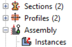
- Assembly>Instances>Select All Relevant Parts>Select Apply>Select OK
- Select Steps (1). Load. Static (General). OK in next window.
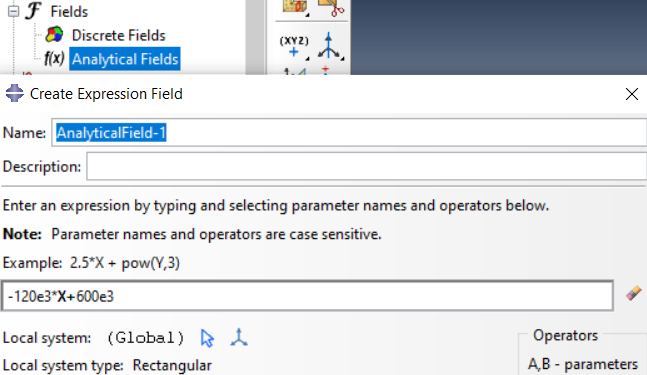
- As per diagram, we establish an analytical field for later use. Input equation and continue.
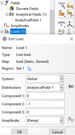
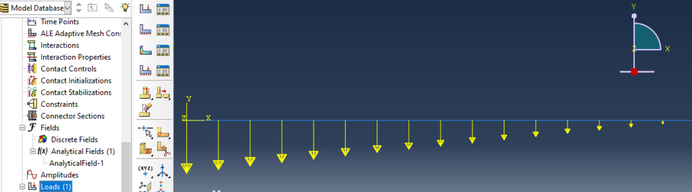
- Select Load. Line Load. Select the AnalyticalField we just created. In the X-Direction we do not have load. 0. We have a Negative Y-Direction load, hence the -1. 0 for Z-Direciton.
- Double Click Jobs. Select OK for default name and default settings afterwards.
- Add Field Output Request. Double Click F-Output-1 and input NFORSCO by searching through forces.
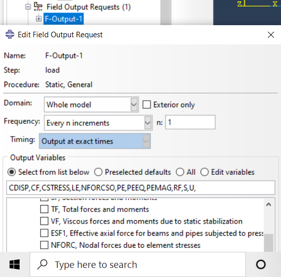
- Right click created job. Select Submit.

- NFORSCO1 is Axial Force
- NFORCSO2 is Shear Force
- NFORCSO6 is Moment
- To plot results onto undeformed beam, long click on icon